Modeling Digital Circuit with Petri Net

Nowadays the continous increase of complexity in digital circuits needs new approaches and tools to support their design. For this purpose we offer the tool Logical PetriNet (LPN) to generate digital circuits from Petri net descriptions. These behavioral descriptions of digital circuits with Petri nets can be transformed into a hardware description language like VHDL.
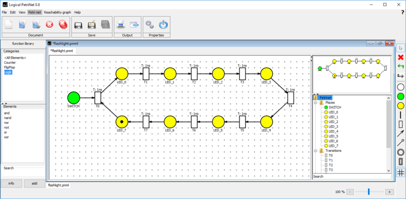
For a description of digital circuits the standard Petri net elements are not sufficient and therefore the Petri net definition needs to be extended. To represent digital circuits with Petri nets, signal inputs and outputs must be defined. For this purpose two new types of places are added. These are on the one hand the input places, represented with a black circle filled green. On the other hand the output places represented also as a black circle but filled yellow.
The readability of Petri nets requires a hierarchical division into subnets. It is necessary that subnets may have multiple input and output arcs to connect multiple items within a net and to present a wiring from outside. The subnets are divided in subplaces and subtransitions. As a further kind of subnet, Petri nets have been expanded with subtransitions, which are used to save modeled Petri nets as function library elements. The subplaces will be used for modeling a hierarchical structure.In order to establish an interface to the outside of a subnet, a new element is introduced and it is called netconnector. These components fulfill different tasks, depending on the subnet. For each input and output arc from or to the subnet a netconnector within the subnet is implemented.
The modeling of the proposed system is realized as a Digital Circuit Petri Net (DCPN). This is followed by the validation of the model to reveal erroneous or contradictory characteristics of the DCPN and to identify these faults in the net. Further strategies will be used to identify potential improvements in the net. Elements without an impact to the behavior of the circuit will be removed in this optimization step. Furthermore this step deals with the detection and grouping of redundant elements.
The next step is a general structural analysis, in which the circuit type must be determined. These circuit types are combinational and sequential logic. Deficient modeling can also appear in this step, because a comprehensive analysis of the system takes place. The DCPN will be transformed to truth tables or input driven reachability graphs depending on the detected circuit type.The transformation of DCPN in the hardware description VHDL affiliates in which the interface of the entire net is created. Furthermore, the description of the behavior or structure is set up depending on the detected circuit type.
After the transformation is completed, a validation of the circuit can be initiated. It will be achieved by a comparison of the simulation results between the DCPN model and the resulting digital circuit.
To support modeling as well as for verification and validation of the presented methods the program Logical PetriNet was created. This tool supports the methods to transform DCPN to digital circuits. The shown figures are steps in the transformation process. In addition, the tool offers the following features:
- Modeling DCPN in graphical description
- Placement optimization
- Universal export interface
- Token game
- Logger and bug report system
- Analyse methods
- Simulation tool
- Creating input driven reachability graphs
- Function element library
